Standard Operating Procedure (SOP) for Preparation and management of Drawings and Layouts
1. Purpose
To provide a standard operating procedure for preparation, review, approval, and management of drawings and layouts.
2. Scope
The scope of this procedure is applicable for the preparation, review, approval, and management of the following drawings and layouts at [company name]:
- Manufacturing facility plot plan
- Facility floor plan
- Facility Heating Ventilation and Air Conditioning (HVAC) system zoning layout
- Facility area classification zoning layout
- Facility pressure zoning layout
- Facility man and material movement layout
- Facility HVAC ducting layout
- Facility equipment layout
- Air Handling Unit (AHU) AHU air flow diagrams
- Water system drawings
- Compressed air distribution line diagram
- Nitrogen gas distribution line diagram
3. Responsibility
Project department: To prepare drawings (using an in-house team or with the help of a consultant) for plant design before plant construction.
Plant engineering department: To prepare/ revise the drawing and layout. Responsibility of plant engineering for preparation or revision of drawing usually starts once the plant is handed over to the site team by the project team after project completion.
Project Head or Engineering head: To check the drawing and layout for its adequacy.
Plant head/ factory head: To approve the drawing and layout.
Quality Assurance head: To approve the drawing and layout.
4. Definitions
Engineering drawing or layout: It is a technical schematic visual of a building, equipment, system, or object. The drawings or layout provide information regarding the dimensions required for the construction and overview of a building, object, equipment, etc.
Manufacturing facility plot plan: The plot plan provides information about the overview of the facility plot, walkways surrounding the facility, location of the facility, number of buildings/ blocks available on the plot. It is good practice to cover the plot area and build-up area of the plant in the plot plan.
Facility floor plan: The floor plan is a simple schematic layout of each floor of the manufacturing facility that provides an overview of the area, room names, room numbers, doors with opening direction, windows, pillars, etc.
Facility Heating Ventilation and Air Conditioning (HVAC) system zoning layout: The drawing provides an overview of the HVAC systems design and AHU connections supplied to the respective areas. For example, the drawing will provide the information that which AHU is supplied to which rooms, which areas have common AHUs, which areas have dedicated AHUs. Each area with different AHU connections should be demonstrated using different legends for easy understanding.

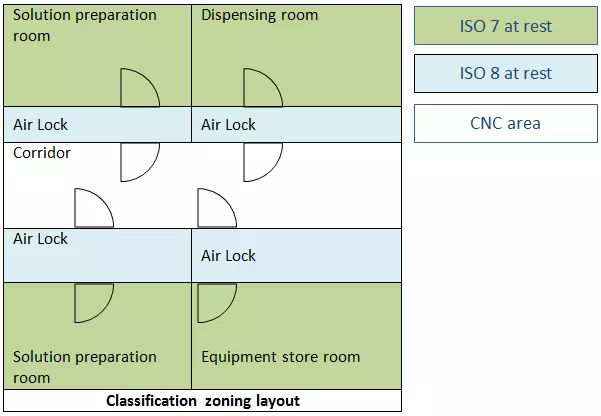
Facility Area Classification zoning layout: The drawing provides an overview of the room classification of different areas.

Facility pressure zoning layout: The drawing provides an overview of the room differential pressure of different areas.

Facility Man and Material movement layout: This drawing provides overview of the man ad material entry in the rooms.

Facility HVAC ducting layout: This drawing provides an overview of the AHU ducting on the service floor and its entry to the respective rooms.
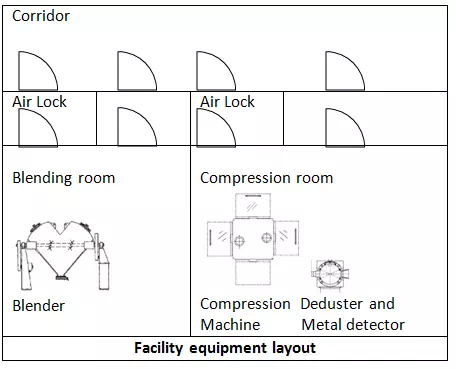
Facility equipment layout: This drawing provides an overview of the equipment placement in the room.

AHU air flow diagrams: This drawing provides an overview of the individual AHU, where it describes the details regarding air filtration scheme, cooling and heating coil arrangement, percentage air mixing (fresh and recirculating air, bleed), airflow volume, air volume supplies to rooms, and air leakages from rooms, etc.
Water system drawings: Water systems are generally consisting of two parts. One is water generation system and another water distribution system. Generation system drawing consists of different components of water system such as multigrade filter, softener, basket filter, UV, RO, ion-exchange units, sampling points, etc. Water distribution system drawings consist of piping distributions, sampling points, user points, distribution pump, UV light, instrumentation, areas where user points are available, etc.
Compressed air distribution line diagram: The drawing provides details of compressed air distribution from generation/ storage to the user points. The drawing consists of details such as level of filtration, instrumentation, user points, areas where compressed air distribution has been reached, etc.
Nitrogen gas distribution line diagram: This drawing provides details of nitrogen gas distribution from generation/ storage to the user points. The drawing consists of details such as level of filtration, instrumentation, user points, areas where nitrogen gas distribution has been reached, etc.
5. Procedure
- Drawing for the facility shall be prepared by the project department at the time of facility commissioning. Subsequently, once the plant is handed over to the site in-charge or location-specific team, the revision or modification of the drawings or layouts shall be done by the engineering department of the site.
- Each drawing should have unique identification number. (Note: The number should be generated in-house instead of using a consultant numbering system to have a uniform numbering system)
- Whenever the initial drawing is prepared by the consultant, in addition to the site-specific numbering system, reference to the consultant drawing should be specified.
- Drawing revision history should be maintained to track the changes made in the drawings.
- Any change in the drawing should be done through the change control management procedure.
- While preparation of drawing, appropriate legends shall be used for easy understanding.
- The drawing should be prepared in such a way that the information available in the drawing should be legible.
- Electronic copies of drawings should be adequately controlled to ensure that while revision of the drawing a recently modified electronic copy is used to update the drawing.
- Drawing should always be printed in color copy for better readability when the color is used to demark the area and zonings.
- After printing the drawing, it should be thoroughly reviewed to ensure that all the required changes have been made correctly.
- Whenever multiple copies of a drawing need to be maintained by the site, it should be managed by the master copy and control copy concept.
- An original copy of the print should be used to create a master copy. Distribution copies should be reproduced by photocopying the master copy in color print. Distribution copies should be made a controlled copy to ensure that only authorized copies are available in the plant and whenever revision is made, old copies can be retrieved.
- Master copies should be maintained by the quality assurance department. Record of control copies distribution should be maintained. Control copies also should be equally legible and preferably should be in color print.
- Whenever revision of drawing is made, the previous version of the master copy should be made obsolete and achieved for future reference. Retrieved control copies should be destroyed as per company procedure and records should be maintained.
- In case of any type of drawing need not be controlled by QA, it should be declared in the procedure with appropriate rationale.
6. Application of drawing and layout
- Facility approvals by government authorities
- Requirement of Site Master File
- To understand the facility at glance
- Requirement by regulatory auditors during inspection to understand the facility design and
- compliance
7. Formats
- Format for preparation of drawing
- Format for list of drawings
- Format for drawing revision history
- Format for drawing distribution

